Home/Product & Services/H2/O2 analyser for nuclear power plants

H2/O2 analyser for nuclear power plants

Our high performance analytical systems have been used in the nuclear industry since 1980. They enable operators to monitor hydrogen and oxygen levels at critical locations within both boiling water reactors (BWR) and pressurised water reactors (PWR).

Contact Us

We can provide a analyser solution that meets your specific requirements. Enquire Now.

Latest sensing technologies are combined with state-of-the-art conditioning to provide an automated approach to gaseous hydrogen and oxygen analysis.

Our industry experts can select from a range of sensors, hardware and software to ensure optimum performance for your application.

See the full range of gas monitoring solutions.

Simple to install

  • Works in inert atmosphere or in air background with no modification to analyser setup
  • No flow controls are required
  • No reagent or nitrogen zero gas flows are required
  • No radiation induced errors
  • No hot catalytic surfaces – not an ignition source

Automatic calibration

  • Calibration is done under full sample flow conditions. This eliminates disruption of sample line equilibrium allowing immediate return to sample analysis following the calibration
  • It consists of a low span/high span application. Automatic and requires less than 30 minutes for the complete cycle

Easy to operate and maintain

  • No custom circuitry – all conditioning modules are standard COTS products
  • Operates at process pressure – no pressure control or regulation is required
  • Operates at process temperature – adding heat only as needed to avoid condensation and maintain sample integrity

The analyser system is arranged as two assemblies:

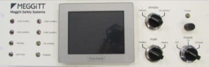
Remote control assembly: This is designed for mild environment locations.

It includes a PLC based control and conditioning assembly, a touch screen display and system switch panel.

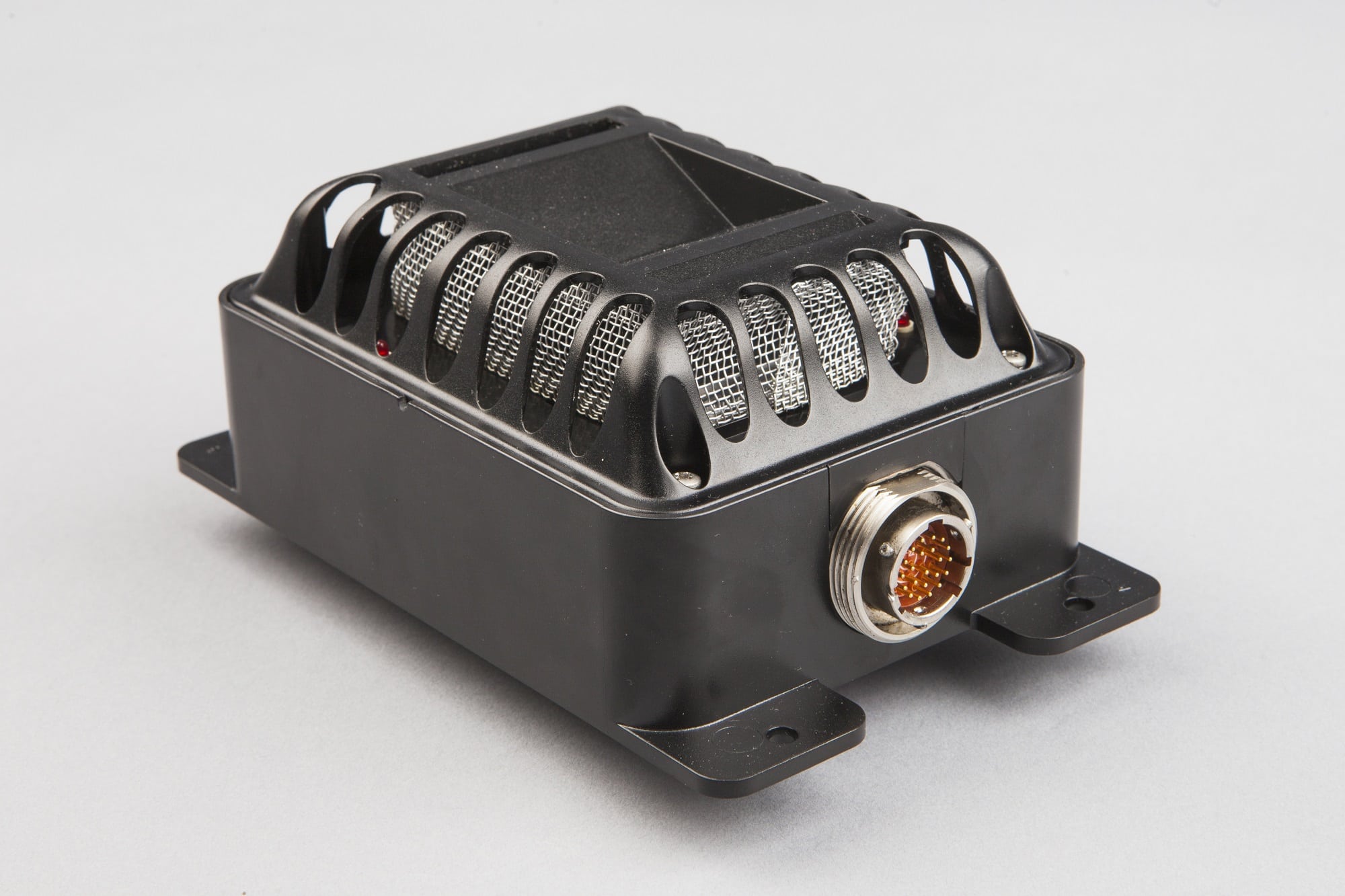
Sample station assembly: This is designed for harsh post-accident conditions.

Components within the local sample station are limited to only those required to extract, measure and return sample to containment. Interconnect between the assemblies is electrical only. All signals are robust and low impedance requiring no special cabling beyond normal considerations for analogue signals.

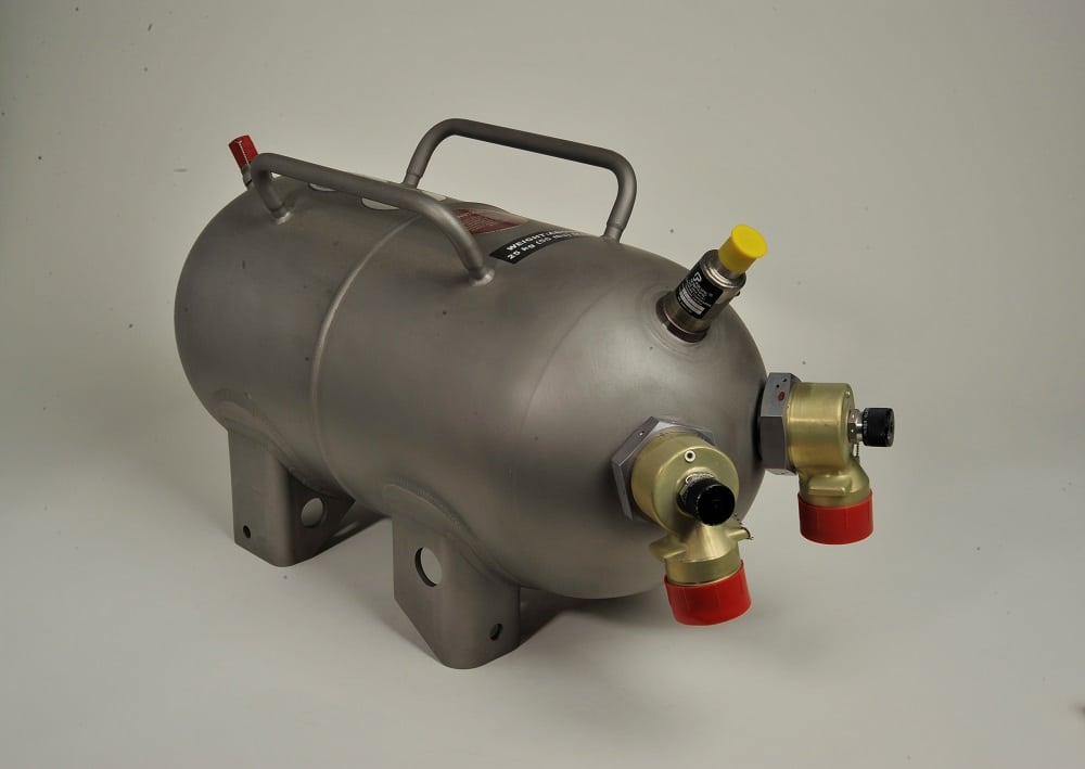
For the INSITU system, the sensors and a local calibration gas supply are mounted on a bracket for installation in containment. (what does this mean?)

Packaging options are available including free-standing enclosures or re-use of existing free-standing enclosures.

Approved for safety categories 2 and 3 (Amended Rule 10CFR 50.44)

PLC Conditioner

The microprocessor assembly contains all of the programming and processing power required for Category 1 CAMS operation, supervision and control. This assembly also provides the primary operator interface via the chassis front touch screen display. It is packaged within a rail mounted enclosure designed for installation into a free-standing enclosure. Once installed, access to the modules making up the PLC may be accomplished by removing the screws retaining the front panel to the enclosure, pulling the unit forward on its slide rails.

The microprocessor PLC includes a set of modules selected to process data accumulated from the local analyser sample station, provide logic output for operation of all sample station ON-OFF functions, provide information to the field in the forms of analogue output signals, alarm contact closures and as a visual display. (need to review and simplify text)

Sample enters the sample loop assembly through SV1, passes through a short section of tubing into a container within which sample liquid content is separated from the sample and collected by a condensate trap. The sample continues onto the detection chamber through a section of heat traced tubing. At and within the detection chamber, all partial and total pressure measurements are obtained. Sample exits the detection chamber, passing through a flow switch and finally through the sample pump used to drive sample out of the sample loop assembly through SV7. FR1 is included to provide the user a convenient method for determining sample loop flow rate.

Sample Extraction System

The mild environment systems are suitable for applications including Containment inerting, Waste Gas Monitoring, and Off Gas Monitoring. Electrochemical sensing technology is combined with “state of the art” PLC based signal conditioning to provide an automated approach for monitoring hydrogen and/or oxygen. The system is arranged in two subassemblies, the Control center and the sample loop assembly.

The Control Center includes a user friendly touch screen human interface (shown) and a PLC (not shown). The sample loop assembly is completely assembled onto a unistrut frame suitable for installation into a free standing enclosure or attachment to plant structure. All sensors and sample handling components are included within the sample loop assembly. The Control Center controls the sample loop assembly and processes all sensor signals to provide the required concentration in units of volume % (wet basis).
(need to review and simplify text)

We can provide an analytical solution to meet your application needs. The selection considers both operating conditions as well as performance needs. Although the technologies used may be extended beyond the ranges shown, typical specifications are as listed below.

Parameter Value
Range: 500 PPM to 100%
Operating Conditions:
Temperature
Pressure
Humidity
-20°C to 152°C (-4°F to 306°F)
0.5 Atmosphere to 5 Atmospheres
0 to 100% (non-condensing)
System Outputs: 4-20 mADC
Visual Display
Alarm Contacts
Alarm Contact Rating: Up to 10 Amps
Calibration Frequency: 3 to 6 Months

Scheduled maintenance tasks have been identified to enhance the overall reliability and accuracy of the system. This is accomplished through the following activities:

  • Provide periodic adjustments of calibration factors to compensate for allowable component drift
  • Verification of overall CAMS operational capability
  • Scheduled replacement of limited life components (parts subject to wear-out or limited by qualified life)

The following is a tabulation of maintenance activities, along with recommended frequency and a brief description of the task. The frequency column represents the maximum interval between performance of the activity. For Category 1 applications, the maximum interval should not be exceeded except under conditions identified in the table.

Activity Frequency Task
Primary Calibration 90 days Initiate auto cal to a partial pressure sensor two point check. Record total pressure for future reference.
Pump Motor Assembly 12 Months Inspect motor mounting hardware and, if Sample Station is normally in Standby, check motor insulation resistance.
Conditioner Status 18 Months Check Transducer Drive Voltage, Power Supply Outputs and DAC Outputs
Pump Motor Assembly 18 Months Verify dead-head pressure.
Rebuild if significant change.
Alarms 18 Months Verify Alarm Functions
Cal Gas Supply 36 Months Check Gas Cylinder pressures and note usage rate. Leak check supply manifold if usage rate is excessive. Update Cal Gas Data if cylinders are changed.
Pressure Transducer
(RTD if Applicable)
36 Months > Perform two point check of the total pressure (and, if applicable, temperature) measurement function. Update factors as needed.
Pump Motor Assembly 36 Months Refurbish pump. If pump operation is intermittent, it can be deferred to 60 months.
Pump Motor Assembly 5 Years Rebuild Pump. If in continuous operation, pump rebuild should be every 36 months.
Partial Pressure Sensors 10 Years Replace Partial Pressure Sensors
Solenoid Coil Replacement 14 Years Replace Coils for 1E Asco Solenoid Valves. Operating life is based on 109°F ambient temperature and may be extended if unit is operating at a lower ambient temperature or is normally in Standby mode.

Station Assembly

The sample station, contains only the equipment required to extract sample from containment, perform the required measurements, and return the sample back to containment. All other system components required to complete the sampling system functions and control are located at the Remote Control Center. This arrangement permits complete operation of the system from the mild-environment Remote Control Center location.

Key customers

Our analyzers are used worldwide in Nuclear power plants to monitor the H2/O2 gas concentration level of Waste or Off Gas post-accident. The analyzers provide critical information in which plant operators can take action to prevent a catastrophic explosion accident.

Our state of the art Nuclear Analyzers are used by power generation utilities worldwide in North America, France, other European countries, China, and Korea. Our OEM customers include Westinghouse, KHNP, and EDF.

Key System Characteristics and benefits:

  1. H2/O2 direct measurement
  2. No Correction/Compensations required for humidity/O2 content
  3. Minimal Maintenance
  4. No reagent gasses
  5. In Situ or Sample Extraction (Amended Rule)
  6. Dissolved H2/O2
  7. Independent of Sample Flow Rate/Total Pressure

For more information, please contact MSSI-SCSupport@meggitt.com .